


Laboratory Space Frame in Ottawa: A Structural Approach for Cleanrooms
An adaptable structural platform for advanced laboratories and controlled environments.
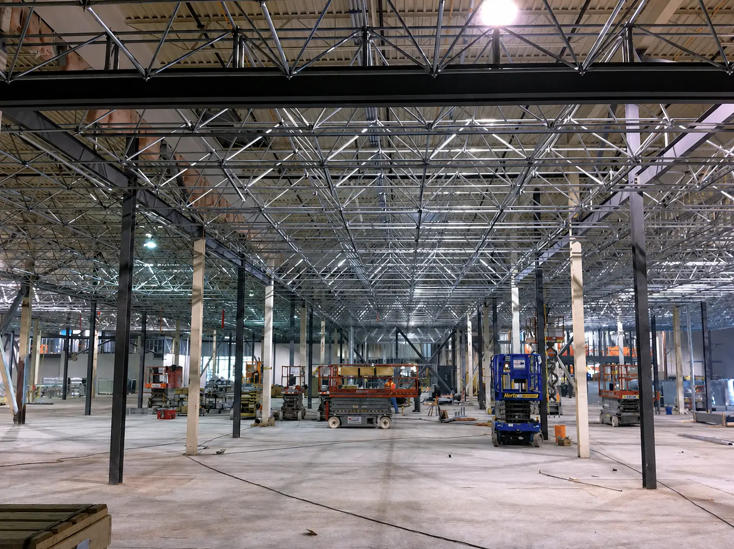
At Kanata Research Park in Ottawa, Ontario, the Flytta Tenant Fit-Up introduced a structural space frame designed to support the services that keep an advanced research facility operating. The approximately 41,400 sq ft (3,847 m²) system created an overhead framework for mechanical, electrical, and future laboratory infrastructure without relying on the existing roof structure or introducing closely spaced interior columns.
The Flytta Tenant Fit-Up was developed for a research and development facility, rather than a certified cleanroom. Triodetic’s scope covered the complete design, supply, delivery, and installation of the steel space frame. The resulting system demonstrates an approach that can be applied to cleanrooms and other facilities requiring adaptable overhead infrastructure.
A Structural Platform for Changing Infrastructure
Laboratories, clean manufacturing facilities, semiconductor environments, and research spaces rarely remain static. Equipment changes, cable trays expand, HVAC systems are upgraded, and process utilities are rerouted as operational requirements evolve.
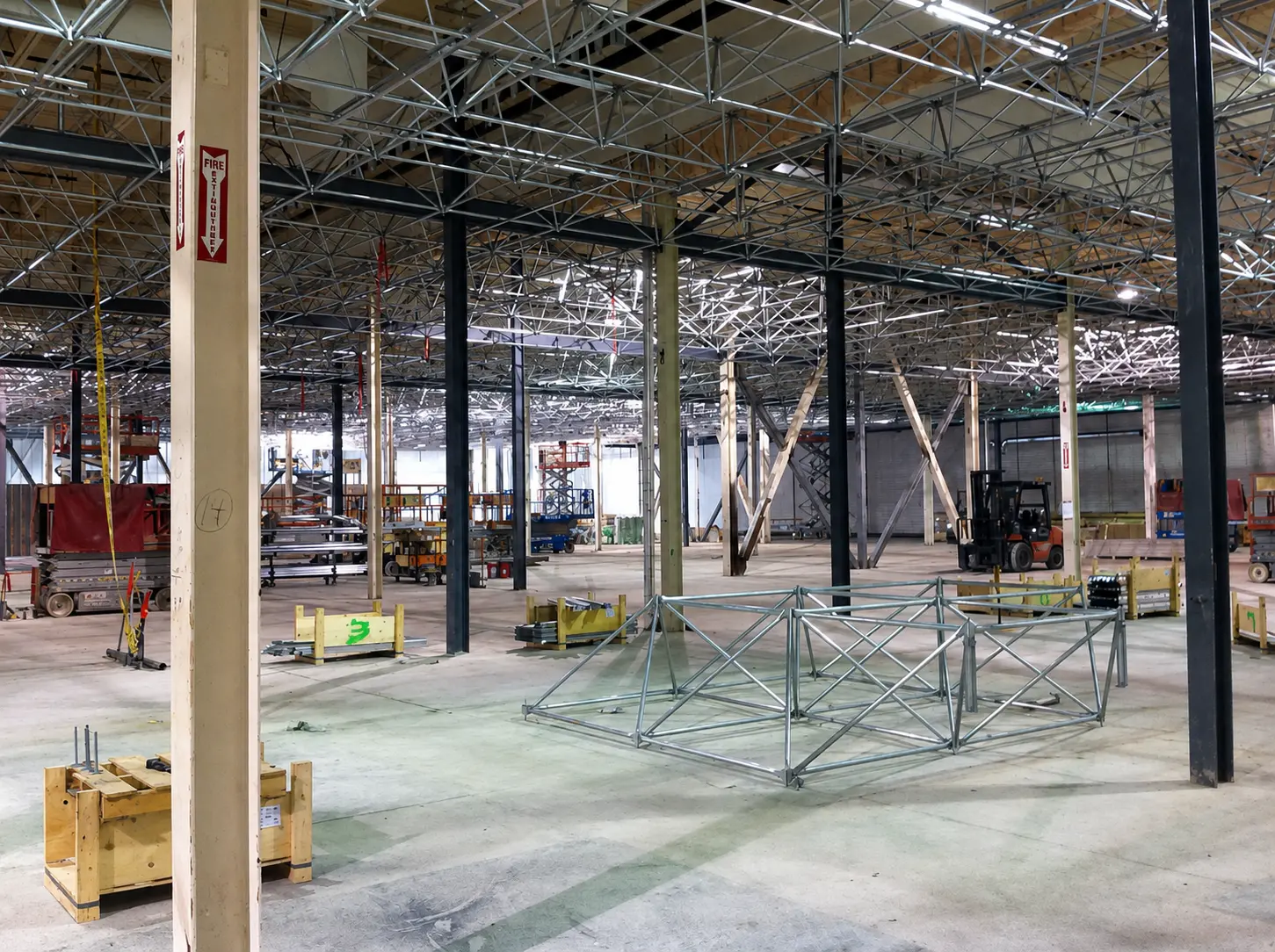
For the Flytta Tenant Fit-Up, the project team needed a structure capable of supporting these changes without repeatedly modifying the building’s primary structure. The solution was a steel space frame installed beneath steel support beams spaced at approximately 9 m centres. Most columns visible in project photographs are part of the existing building and were not structurally required by the space frame.
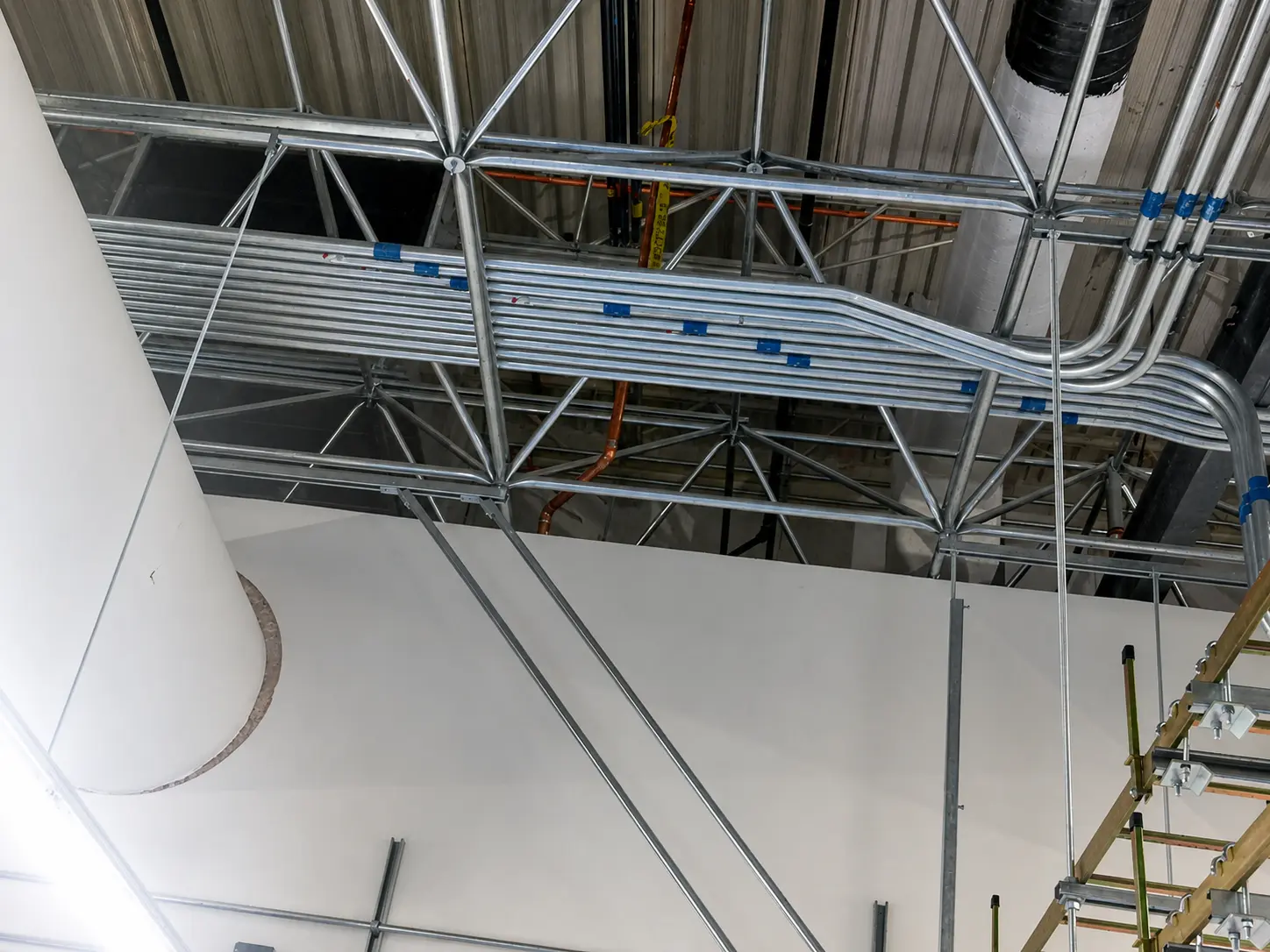
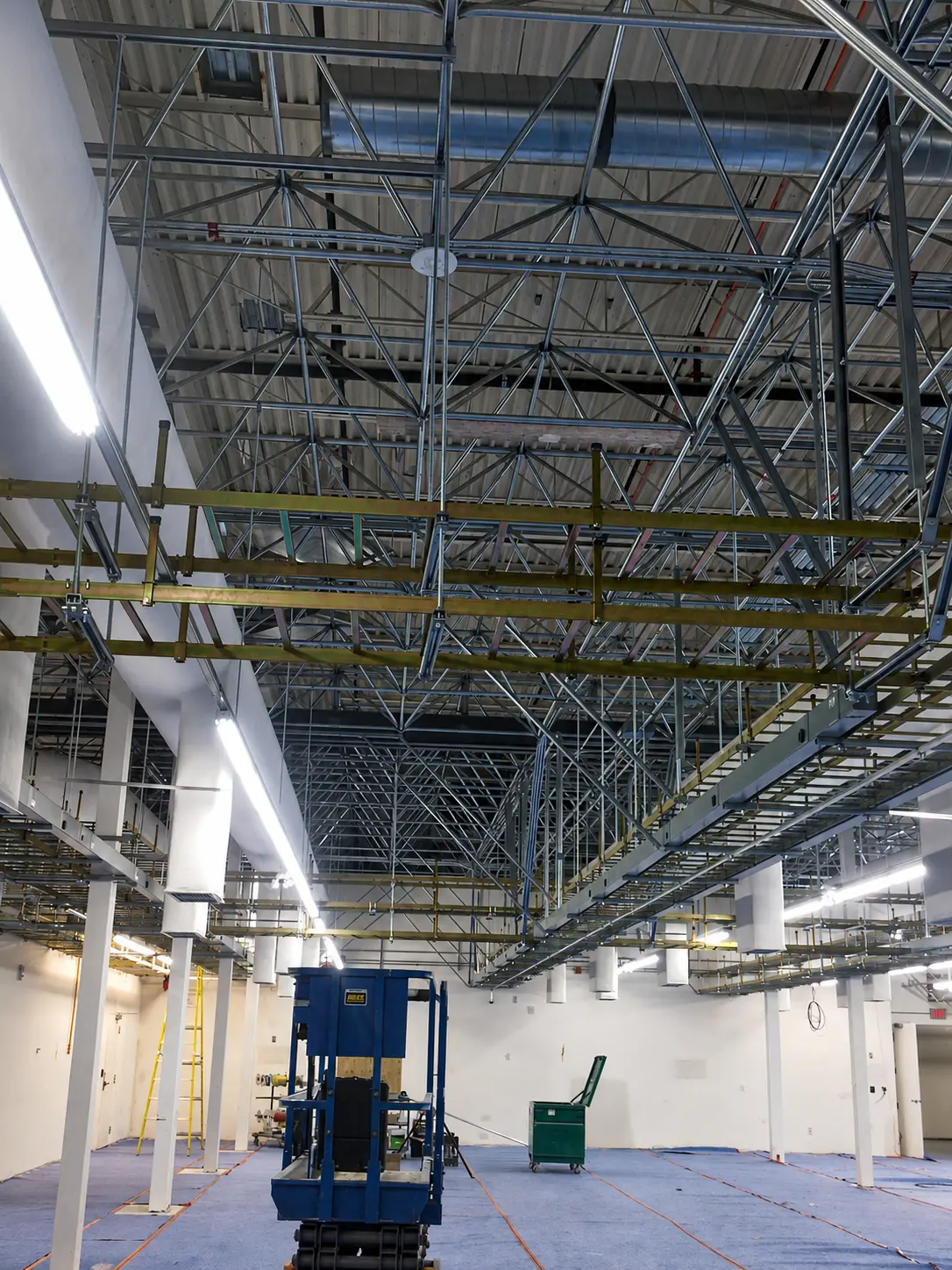
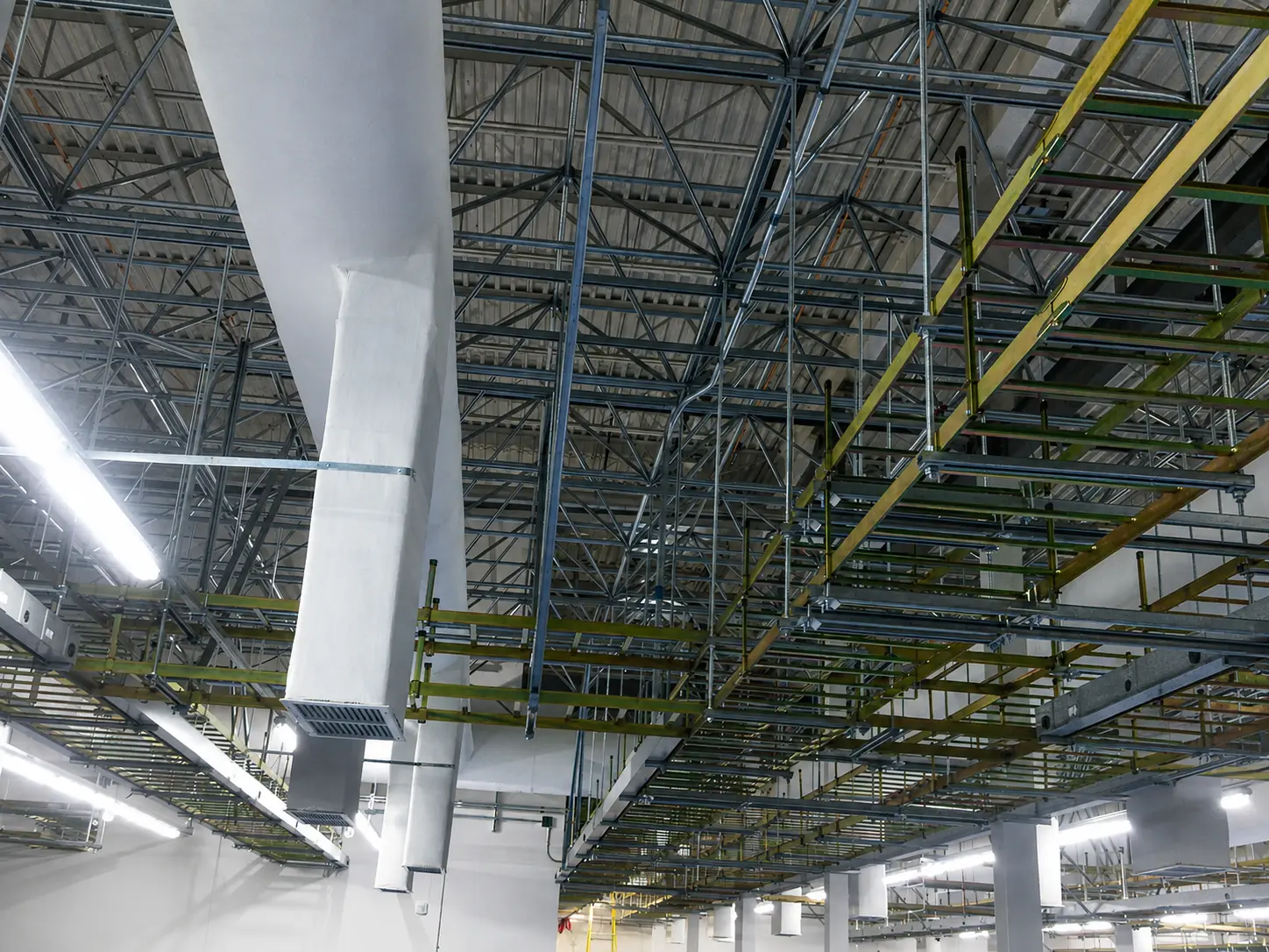
The space frame was designed for a 1.5 kPa superimposed load, in addition to its own self-weight and specified stacked cable tray point loads. It created a permanent utility platform that could support lighting, sprinkler piping, cable trays, HVAC ductwork, filtration systems, laboratory utilities, and future tenant improvements.
Designing Around Flexibility
A key engineering decision was the selection of the module size. A larger module would have required fewer tubes and connections, reducing the number of structural components. A smaller module, however, would provide more frequent attachment locations and more flexibility for future mechanical and electrical layouts.
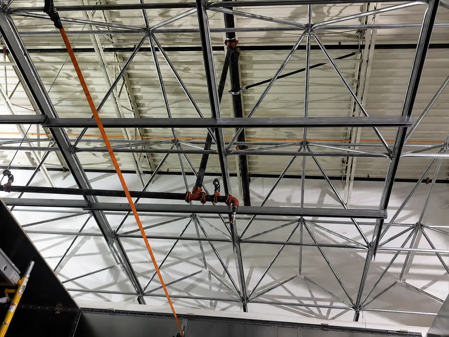
The project used a 1.5 m module. This approach created a dense structural grid across the facility, with thousands of potential connection points for future services. The module spacing could also be adjusted where required to accommodate expansion joints and variations in the supporting beam layout.
The system included light-gauge galvanized steel framing elements at partition wall interfaces. These elements spanned between bottom chord nodes, allowing partition walls beneath the frame to be positioned independently of the module spacing before being carried horizontally to the nearest chord line.
This detail allowed the structural grid and interior planning to work together. The space frame did not impose a fixed layout on the laboratory floor below.
A Space Frame Engineered for Overhead Services
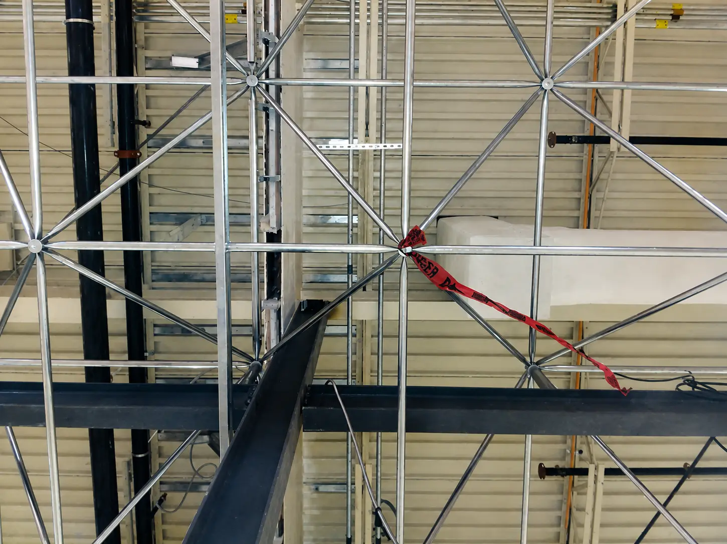
The completed structure covered 41,408 sq ft and incorporated 13,209 structural tubes and 3,488 aluminum Triodetic hubs. Primary members included 1.5 in x 0.095 in chord tubes and 1.25 in x 0.095 in diagonal tubes.
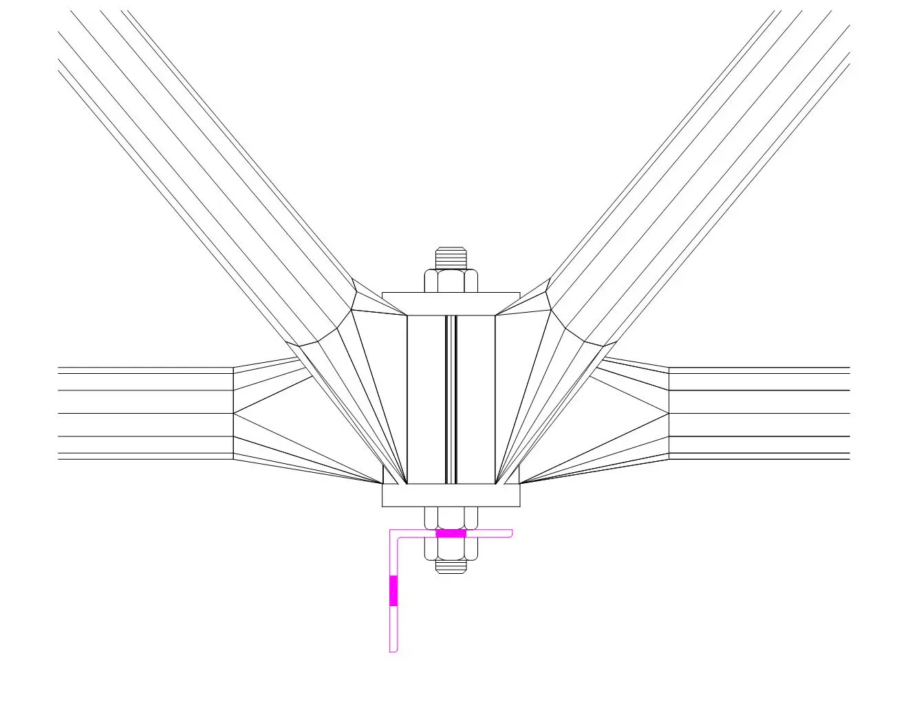
The attachment guidelines defined a practical approach for future mechanical and electrical work. Mechanically fastened hangers or clamps could be used for standard services, with connections generally located close to tube ends. Heavier individual attachments and cable tray loads were directed to the connector hubs, where the structure was designed to receive them.
The project-specific guidelines placed mechanical connections as close as possible to tube ends, within 10 in (250 mm). They limited the total attachment load at a single hub to 216 lb (98 kg) and mid-span tube loads to 30 lb (13.6 kg). Individual attachments that exceeded those limits, along with heavier cable tray loads, were required to connect directly to a hub.
These criteria gave future facility teams a clear framework for expanding services while protecting the structural integrity of the space frame.
Prefabrication and Installation
Triodetic’s scope included complete engineered shop drawings, material lists, Ontario engineering stamp, support reaction information, installation drawings, and installation instructions. The materials were fabricated in Arnprior, Ontario, using galvanized steel tube components and galvanized miscellaneous steel components.
Fabrication included tube coining, aluminum hub machining and drilling, threaded rod cutting, connector plug production, strut fabrication, hat channels, minimum-span clips, brackets, clip angles, and purlins. Preparing these components before site work turned installation into a coordinated assembly process rather than extensive field fabrication.
Crews assembled manageable sections on the floor before lifting them into position with a forklift. Three scissor lifts supported the installation team as each section was connected to the growing structure. Since the building was not occupied, crews could assemble large sections while maintaining safe access. For structures of this type, installation can be planned at approximately 1,000 sq ft per day.
Space Frames for Cleanroom Infrastructure and Advanced Manufacturing Facilities
The project demonstrates a structural approach for cleanrooms and other facilities that require extensive overhead mechanical, electrical, and process services. A dedicated space frame can provide a planned framework for these systems while preserving larger unobstructed areas below.
This approach can be considered for semiconductor fabrication, pharmaceutical manufacturing, biotechnology laboratories, aerospace facilities, battery manufacturing, data centres, research environments, and certified cleanroom projects, where specific environmental requirements must be defined for each application.
Technical Specifications
- Project: Flytta Tenant Fit-Up
- Location: Kanata Research Park, Ottawa, Ontario
- Structure type: Steel space frame
- Coverage area: Approximately 41,400 sq ft (3,847 m²)
- Module size: 1.5 m
- Design superimposed load: 1.5 kPa
- Attachment guideline: Connections as close as possible to tube ends, within 10 in (250 mm)
- Attachment guideline: Maximum total load at one hub, 216 lb (98 kg)
- Attachment guideline: Maximum mid-span tube load, 30 lb (13.6 kg)
- Structural tubes: 13,209
- Triodetic hubs: 3,488 aluminum hubs
- Chord tubes: 1.5 in x 0.095 in
- Diagonal tubes: 1.25 in x 0.095 in
- Tube material: ASTM A500 round steel tubes with factory pre-galvanized finish
- Installation planning allowance: Approximately 1,000 sq ft per day
- Installation equipment: Three scissor lifts, one forklift, and welding equipment
- Documented Triodetic scope: Design, supply, delivery, and installation of the space frame structure, including shop drawings, support reaction information, installation drawings, and installation instructions
The Flytta space frame shows how structural engineering solutions can give facilities a long-term framework for change. For advanced laboratories and controlled-environment applications, the structural system is not part of the environment itself. It is the adaptable overhead infrastructure that can help the facility evolve.
Contributors:
Luis Infanzon (Marketing Coordinator)
Executive Contributor

